Obsolescence Guaranteed
Recommended: Gigatron
a computer w/o a microprocessor

We're moving to a new site
Now there are so many people involved in the PiDP replicas,
it's become time to move things to a new group web site.
Use the button below for the new Building Instructions page;
although I'll keep the old version down below for a while yet.
Building Instructions
This page is for the 2019 version of the kit.
For the oldest 2015 version, please go here. For the previous 2016-18 version, please go here.
Building the PiDP-8 should take about 4 hours. Tools required:
-
Soldering iron, side cutter, Phillips screwdriver with 2-2.5mm shaft, and (ideally), a drill.
Parts list
-
1 PCB, 1 case, 1 acrylic front panel,
1 LED cover bracket -
11 brown & 9 white toggle switches
-
1 brown & 5 white momentary switches
-
1 40-pin extra-height Pi connector
-
89 yellow 5mm LEDs, 89 LED spacers
-
27 diodes
-
1 UDN2981A or equivalent IC + 1 IC socket
-
12 resistors (390 ohm), 3 resistors (1K or 820 ohm)
-
3 wooden mount blocks to fit PCB in case
-
6 M3*9.5mm screws:
4 to fix blocks to case back,
plus 2 to mount PCB on small blocks -
2 M3*16mm screws:
to mount PCB on tall block -
3 M2.5 spacers + 3 bolts + 3 nuts:
to mount Raspberry Pi to PCB -
No longer in kits as of Nov. 2021:
2 M3*30mm screws to mount front panel;
these 2 screws are normally left unused!
Some spare parts are included in the kit.
You need to supply your own Raspberry Pi (model A+/B+/2/3/4/Zero/Zero W).

A major thank-you to
Warren Young and Dr. Bill Cattey
The download links point to the Tangentsoft web site. Warren, Bill and many others have put tremendous effort in polishing up both the PiDP-8 and PDP-8 software over the last few years. It's hard to fathom how much work has gone into this.
Their software, codename: pidp8i, is the 'Official' PiDP-8 software.
To avoid confusion:
There used to be mention of my own 'original' PiDP-8 software from 2015 here (Codename: pidp8 without i), but that version should no longer be used.
When reading older posts on the PiDP-8 Google Group, remember the above to avoid confusion!
Most people just go off soldering the kit. It is a simple kit and indeed the text is too long with all its exhaustive detail, meant for the lowest common denominator in skills. But really, READ the details. It WILL save you time in the end: all the details builders ask about were already explained here.
1. Prepare & test your Raspberry Pi
The pidp8i software runs fine without the actual PiDP-8 board plugged in. It is a good idea to test and set up your terminal connection before you start with the hardware. If, after the steps below, you see the OS/8 command prompt, then you will also see the front panel blink once you have soldered it up.
There are multiple install options (see here) but in these instructions we will take the route of installing the pidp8i software on a freshly up-and-running, regular Raspberry Pi. You will plug it into the PiDP-8 board later on.
Here (link) is the short copy-and-paste set of instructions.
Only if you are entirely new to Raspberry Pis: visit the Raspberry Pi software page (link), watch the 45 second video (link), and use their Imager program to make the SD card. After that, there is this older PDF (link) with some older but still useful tips. It's meant to set up your Pi *before* you install the PiDP-8 software. So it does not have anything to do with PiDP-8s - just with basic Pi management, which will come in handy anyway. Feel free to email me with any setup questions, no problem.
Only if you use the old Pi Zero (W): the pidp8i software is autoconfigured to 'glow' the LEDs like lamps on a Pi 2/3, but it must be configured to only 'blink' the LEDs on the Pi Zero (W). That is much less CPU intensive. Lamp glow emulation is sweet if you have memories of it, but takes too much of a load on the humble Zero. Read the README.md file in the pidp8i directory you just created for setup details for the Pi Zero.
Depending on how you want to set up your Pi, the PDP-8 terminal can come up straight after you log in, with OS/8 running; or you have to enter pidp8i to access it. Even though the physical front panel is not attached yet, the PDP-8 is running. This is what you should see - if you do, basic setup is done:

Using LED spacers - 3 steps

For now, you can escape out of the PDP-8 for an orderly shutdown:
Ctrl-E, exit, and then sudo shutdown -h now
2. Soldering
The #1 problem with kits is bad solder. Good solder flows, bad solder clings to your iron. It's a huge difference. I like Stannol HS10, but google for other good brands (leaded, 0.5-1.0mm). The #2 problem is bad soldering irons. A good one has a temperature control knob or something like that. A bad one is a soldering iron with a big tip, plugging straight into the mains: they are meant for plumbing, not electronics. It may be OK, but use those at your own risk.
Pause to think on which side of the PCB components should be soldered. Everything goes on the front side, except the 40-pin Raspberry Pi GPIO connector.
-
Start with fitting the 26 diodes below the switches, and the 27th diode close to the IC footprint. For diodes, polarity matters: check that the black stripe on the diode matches the white stripe on its PCB footprint.
If your PCB has the diodes above rather than below the switches: at the top of the page, select the 2016-18 version of this kit! -
Proceed with the 3 resistors (1K or 820 ohm in recent kits) above the row of diodes, polarity does not matter for resistors.
-
Then, the row of 12 resistors (390 ohm) above the bottom row of LEDs.
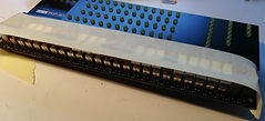
Now come the LEDs. Polarity matters: long leg to the left. To eliminate any uncertainty, see the little drawing of a LED on the PCB, to the right of the LED labelled DAC12.
The LEDs need to be pushed onto the provided LED spacers, so they come out a bit higher on the PCB. Put LEDs + spacers into the PCB. Once all are inserted (not soldered yet), push the LED cover on top of them with a small amount of force. The top 1mm or so of each LED will peek out of the cover. Make sure (by looking from aside) that all of them are like that. Push around them to make sure they sit equally high. Now: flip around the PCB, check if their long legs indeed are all on the correct side, and solder up 1 pin of each LED. Verify the LEDs still sit flush and solder up the other pins. You can remove the LED cover now, and reseat it later. The LED cover is intended to be on the LEDs permanently, once you're finished.
LED spacers are actually a great help when putting in LEDs. But only when you know how to use them; see the pictures. The solid end of the spacer goes towards the PCB, the hollow end faces the LED. #1: Put the LED halfway into the spacer, with its pins only protruding a bit. #2: Mount the LED+spacer onto the PCB. #3: Once the LED is in, press it in all the way. The LED is solidly in the right place.
There are two extra LED footprints without markings on the PCB. They are to be left empty. These are for a Straight 8 replica instead of an 8/I, but would require a different acrylic panel.
-
Solder the IC/chip socket on the front side of the board, with pin 1 facing leftwards.
-
Solder in the 40-pin header that will connect to the Pi. On the back side of the board! Solder 1 or 2 pins first, check the connector sits neatly perpendicular to the PCB. Then solder up all the pins.
-
Mount the Raspberry Pi onto the PCB. There are 3 sets of bolt-spacer-nut (I do know there's 4 mount holes on a Pi. But you only need 3 to make a stable mount thanks to the GPIO connector).
-
It is necessary to insulate the metal casing of the Pi's USB and Ethernet connectors with a bit of plastic or cardboard, they are quite close to the PCB. Just sticky tape has been proven insufficient!
Picture below: the PCB so far. Don't worry if your LEDs are not perfectly in a straight line. The LED cover panel will force them into perfect alignment when you put it on!
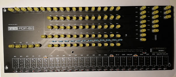
PiDP-8/I: RECREATING THE PDP-8/I
CELEBRATING 50 YEARS OF PROGRAMMED DATA PROCESSING

Nut, bolt, and spacer to mount the Pi on the PCB. There are 3 sets of nut/bolt/spacer in the kit.

For testing: shorting pins to simulate a switch. You could use any metal object, no risk of damage.
3. Quick check
Check if everything works before you solder in the switches. If something does not work, you should fix it now. Any problems should be easy to fix, but in case of Total Disaster: then the PCB with electronics components is actually the cheapest part of this kit. The switches are expensive. If all else fails, I just send you a new PCB and a new bag of electronic components, and you’ll not be much poorer (this was needed in less than 0.1% of kits so far, so don't worry).
First do a visual inspection for shorts caused by solder blobs, and for forgotten solder points (main cause of problems). Then, mount the Pi (It is necessary to insulate the metal casing of the Pi's USB and Ethernet connectors with a bit of plastic or cardboard, they are quite close to the PCB. Just sticky tape is insufficient!) and power up. The front panel will light up (check) after 40 seconds or so, when the Pi has booted up and you find yourself at the OS/8 "." prompt (type pidp8i to grab the PDP-8 terminal f you are not at the prompt, but the lights should come up anyway).
Now, stop the PDP-8 simulation and run a dedicated test program:
Press CTRL-a d , then enter pidp8i stop <return> pidp8i-test <return>
-
LED test: All the LEDs will light up, then turn off when you start pidp8i-test. If one of the LEDs did not light up, identify its name and determine its row and column: Each 'row' of LEDs will be turned on in sequence by the program, and each 'column' of LEDs after that. Pinpoint the row and column numbers with dead LEDs. Details of the test program are here (link).
-
Switch test: Once you are at the program stage where a single light races across the LEDs, you can test the switch connections. Use a metal object (a clipped-off wire from the diodes is ideal, see picture) to simulate pressing each of the switches, and the program should respond with a changed switch value (it should be 0000 0000 0000 if no switches are set). You can do no damage with this shorting out of switch contacts.
Temporary at December 2019: if the switch values come out as 0037 0037 0037: are you using a Pi 4? Not a hardware problem. You didn't add the Pi 4 software patch. See the linked page in section 1, it tells about installing the Pi 4 patch from the Fossil repository. Please email me if you're confused about how to do it!
If you detected a problem, then check the Troubleshooting page. From experience: it is always a bad solder connection, not a bad part. Email me if you can't fix the problem. It will be fixed, don't worry :)
Power down the PiDP (sudo shutdown -h now, and wait 15 sec before powerdown).

Colour and type of each switch marked on the PCB
Alternative, faster way to solder switches (more risk of damage through heat&reseat, but fine if you are an OK solderer)
Put in all switches, tape them together...
... then flip over the board and solder only the top left pin of all switches. Reheat pins & reseat its switch by pressing down on them afterwards. Warning: more risk of heat damage to PCB & switches. Know what you are doing or follow the procedure to the left.

4. Soldering the switches
The PCB indicates where B(rown)/W(hite), and T(oggle)/M(omentary) switches go. Toggle switches click On and Off. Momentary switches spring back. Make sure you:
(A) solder the right switch into the right place, and
(B) don't solder momentary switches in upside down.
The switches have 7 pins: two on top, two at the bottom, and three in the middle. If your switch has only the three pins, go to the top of this page and select the 2016-18 version of the kit!
Momentary switches are all operated by temporarily depressing the lower part of the switch. So mount them such that you momentarily press on the bottom half of the switch to actuate a signal. People get this wrong regularly. The 6 momentary switches have their lower half sticking out to the front unless you depress them momentarily.
Do not overheat the switches: don't set your soldering iron to a very high temperature, and press it no more than a few seconds against the switch. But you'll need a few seconds, because the pins are a big heat sink. Just don't keep the iron pressed longer against the switch pins than the minimum necessary time and you'll be fine.
Start with plugging in each switch, following the BT/WT/BM/WM labels. Be aware of the risk of plugging momentary switches in upside-down. For each switch, only solder the top left pin, whilst pressing against the switch so it sits neatly perpendicular to the PCB.
Once you are done, you will probably see that not all switches sit as neatly in line as you would like. That is completely normal, how it should be at this stage. Look along the line of switches from all sides: are they lined up straight, not slightly bulging in an arc? Look from above and below: is the space between each switch pair the same? If not: briefly reheat the soldered pin of a noncompliant switch whilst you press down on the switch so it reseats itself.
Note: you will always have some slightly varying spacing between switches. That's OK. There is some play in the switch hinges anyway, and once the acrylic panel is put on, a .25mm difference in spacing between switches is no longer noticeable. The real PDP-8/I had much more irregularly mounted switches than your PiDP for sure.
Now take a break. It really matters. When you come back, check once more from all angles if the switches are mounted straight, upright, neatly in line. If they are, solder up the middle three pins. No need to do the other pins unless you really like to do a bit more soldering ;)
Click to enlarge:

A recommended setup with Pi Zero, the standard Pi power cable (the Zero can be fed by a laptop USB port!) and a USB hub. The big slot in the back is optional, it is handy for swapping SD cards though
5. Deciding on the back of the case...
You'll have to decide what holes to drill in the back of the wooden case. It depends on what your preferences are. Short story: you need a hole to lead cables from the Pi to the outside world. Long story:
Use a drill to make slots the easy way. Start with a small hole and use increasingly large drill bits. That avoids stressing and potentially cracking the case.
-
If you keep it simple, and I recommend that you do for now:
drill (or just cut, an Exacto knife will do) a small hole in the back of the case to bring in the Pi's micro-USB power cable. You then log in to the PiDP-8 over wifi using ssh terminal sessions (and VNC over wifi if you want graphics).
-
The next option you could consider is to lead through the connector cable of a small USB hub. The hub can be stuck to the back of the case with double-sided sticky tape, and it'll give you all the I/O you will need. Especially this one as it has an Ethernet port (link for the Pi Zero, link for the Pi 2/3).
The picture on the left shows the end result. Two comments on it: here, I cut a second, very large slot in the back so I could access the Pi's SD card (check carefully where the slot should be though, the picture is of an older-version PiDP-8). That big slot is really not necessary, unless you want to swap SD cards regularly. If, like me, you are a bad woodworker and you end up carving a rather ugly slot in the case back: no problem, just cut a neat bezel to cover it, from a sheet of plastic or something.
-
The idea always was that you would the PiDP with a terminal (either wireless ssh sessions from your laptop, or a real serial terminal using a USB-Serial adapter cable). And if you want to use the Raspbian GUI, you'd use VNC to get that over wifi.
But nevertheless, you may want to connect a HDMI monitor anyway. A HDMI cable will fit the Pi in the case, as long as its connector is of normal size. But it is a tight fit. Mount the Pi with the HDMI cable already inserted into it.
- Another option is to lead an SD Card extension cable (around $2.50, link) out to the back of the case. This way, you can replace the SD card without ever opening up the case again.
One last consideration: Raspberry Pi's Model A+/B+/Zero W can be powered from a laptop's USB port! But the Pi 2 and especially Pi 3 cannot. They need their own power supply or you'll have trouble someday with corrupted SD cards. And I strongly recommend the Official Raspberry Power Supply. It gives out 5.35V, and especially with the Pi 3/4 it does so for a very good reason.


6. Mounting PCB and acrylic panel into the case
There are 3 blocks of wood in the kit to mount the PCB in the case. The blocks of wood are first screwed onto the back of the case. If you have a drill, please drill a 2mm hole for any screws before you use the screws. It makes it much, much easier to be precise.
A. Place the long block against the bottom inside of the case. It will support the switches. Screw it to the back of the case with two of the 9.5mm screws. It should rise up 3.4cm, so you put the screws in to the narrow end of the block. You do not put the block 'flat' so it would only rise up 1.6cm. The length of the block is slightly less than the space in the case. Horizontal placing: Put the block in the middle, so you have something like 0.6mm to the left- and right-hand side of the case.
B. Place the small blocks in the top left and top right corners of the case. Use another 9.5mm screw through the case back to fix them in place. Here, the two blocks must rise up 3.5mm tall. Check to see that you do not have the block rotated in any other way! They must rise 3.5cm.
C. Lead any cables through the back of the case into the Pi before you screw down the PCB in step D.
D. Place the PCB into the case. Its bottom must be against the bottom of the case. The PCB is slightly smaller than the case. Its right-hand side must be flush against the right-hand side inner wall of the case, or maybe up to 1mm offset from the right-hand side: there can be a 1mm variation in the wooden cases, annoyingly.
This is a good moment for an alignment check.
(1) Fit the acrylic front panel on top of the case for a moment and check that the switches line up neatly with the brown/white bars above them. It might be that you want to shift the PCB a millimetre before screwing it down in place in step E.
(2) If you are a perfectionist (why not!), you might find that the three wooden mount blocks could be 1 or 2mm taller than they really are. I often put a bit of cardboard between wooden block and PCB (or between block and case back) so the top of the LEDs sit almost flush against the acrylic panel. It does not matter much, but why not.
The reason for this: not all wooden cases are 100% the same height, and I have to choose the safe maximum height for all of them when cutting the blocks. Apologies: this imprecision is the consequence of using a wooden case (they're handcrafted real wood artisanal products, blah blah).
E. Screw the PCB onto the wood blocks.
-
Make sure the PCB does not shift away from their intended position whilst you do so. Drilling a hole for the screw first makes life a lot simpler.
-
Below, two 16mm screws at either side of the row of switches. After drilling (with the PCB in for precise location determination), take the PCB out and insert the two 16mm screws in to the PCB, then reinsert the PCB into the case. The screws are hard to get in if you try any other way...
-
As you will see, the solder pins of the switches protrudes from the back of the PCB. Problem: if you screw down the PCB, the PCB will flex as the switch pins are in the way. Solution: there is a self-adhesive felt pad in the kit. Use scissors to cut it up in a few pieces and stick those around the two bottom screw holes. They will prevent this problem! When screwed down with normal force (don't overtighten), they have just the right thickness to compensate for the switch pins. You should only use part of the provided felt pad - the rest of it is spares.
-
At the top left and right, a 9.5mm screw will finish off the job.
-
If you want to use a HDMI cable, insert it in the Pi before you mount the Pi+PCB into the case but after you have drilled the screw holes.
Just to check: did you mount the LED cover panel onto the LEDs? If not, do so now.
Now mount the acrylic front panel:
-
It often has a peel-off protective plastic on its front. But do not try to peel off the white paint on the back. That's the panel artwork itself ;)
-
Place the acrylic panel into the case. You might have to force or bend/flex it in before it clicks into position. These panels do not break if you bend them into an arc to fit them in. Bend it in!
-
Check if you can flick the front panel switches up and down without hitting the acrylic.
--> If not, then you've mounted the PCB incorrectly on the wood blocks. To get it right, the previously drilled holes may just be slightly off and you find they can't be corrected without making the drill holes too large. So remount the mount blocks upside down and start again with fresh drill holes.
It used to be that the last step was to use the long 30mm screws in the kit to fix the acrylic panel to the case. It involves drilling two small holes in the panel.
But all builders (me, too) ignored that last step because they find that friction-fitting the acrylic in the case keeps it firmly enough into its place. If the panel sits too loose in the case: the following how-to sounds unprofessional (because it is) but everyone prefers it over the screws anyway:
-
Small bits of (preferably black) sticky tape invisibly placed inside the vertical edge or corner of the case make the "friction fit" work out just fine. Or some narrow strip of very very thin cardboard.
-
I know it sounds unprofessional. But because everyone these days prefers it over using the 30mm screws, I suggest you try this too. Although I kept the 30mm screws as part of the kit "just in case", you should not need them. Contact me if friction-fitting the panel does not work for you. There are some household tips I can provide for maximum satisfaction ;)
You are done!
And now you are done, you might be happy with having your terminal connection over Wifi ssh and VNC sessions, or HDMI, but there are other options: terminal connections to the PiDP-8.


