Obsolescence Guaranteed
Recommended: Gigatron
a computer w/o a microprocessor

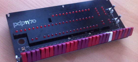
PiDP-11: RECREATING THE PDP-11/70
The PiDP-11: Technical Details
From a hardware perspective, the PiDP is just a frontpanel for a Raspberry PI. In the hardware section below, the technical details of the front panel are explained. In fact, the front panel could just as easily be driven by any microcontroller (or FPGA), it only lights the leds and scans the switch positions.
From a software perspective, the PiDP is just a Raspberry Pi, running Raspbian, which automatically logs in to the SimH 'BlinkenBone' emulator. BlinkenBone has a client (the simh emulator in fact) and a server (the code that drives the front panel). Driving the front panel means reflecting the state of the PDP-11 CPU through the leds, and responding to the switch settings.

1. Hardware
The Raspberry Pi has a 40-pin GPIO connector with just enough I/O pins to drive the front panel. The PiDP schematic is actually taken from the venerable KIM-1 single board computer, and I used it for my earlier KIM Uno and PiDP-8 replicas too. A multiplexing scheme is used to quickly light up alternating rows of leds in sequence. Doing so approximately 60 times per second, with the switch positions scanned in-between, the human eye sees the whole front panel light up.
The figure below gives the basic idea. Three groups of GPIO pins are used:
-
6 'ledRow' pins, each of which provides a collective power line ('+') to a row of 12 LEDs.
-
12 'column' pins, which are connected to the cathodes ('-') of the individual 12 LEDs across all ledRows. So a row of LEDs is powered up when a ledRow pin is set to Output High. Which of the 12 LEDs actually lights up depends on whether its column pin is set to Output High (LED off) or Output Low (current flows, so LED lights up).
-
3 'row' pins each provide a power sink (0V) to a row of 12 switches. The column pins above, when flipped to Input mode with pullup resistors, can then sense which of the switches is 'on' (because that causes a short from row to its column pin overriding its weak pullup resistor).
The software quickly cycles through the 6 ledRows, setting each them High in sequence. Do it fast enough and the human eye sees all rows light up consistently without flickering. Then, the 12 column pins are quickly flipped over to being input pins to sense their attached switches, and the cycle starts afresh.
The simplified animation below pretty much illustrates the principle. Click to zoom:
Download the high-res PDF schematics from the PDF viewer above. (20180406: Apologies, the schematics are not laid out very elegantly. I will clean it up later)
Circuit board layout
The PCB is made in Kicad (what would we do without Kicad!), and using freerouter. It is a very simple affair, as it's all simple point-to-point wiring from the GPIO pins to the LEDs and switches. Note that the rotary encoders are effectively switches too. There are two 'complications': first, the LEDrow pins demand more mA than the Pi can provide. Therefore, a UDN2981 (or modern equivalent) chip acts to buffer these lines and provide more current to the LEDs. Secondly, all the GPIO pins are protected by resistors to limit the load on the GPIO pins. 390 ohm resistors limit the current to the LEDs; 1K ohm resistors limit the current sunk during the switch sensing.
Click on the front and back pictures below for high-res images.


Option areas on the PCB
There is a prototyping area at the top of the PCB, in the hope that builders will add interesting sensors and other simple 'Arduino style' peripherals to the PiDP-11. See the HACKS page for some more detail. Note that the I2C port of the Pi is free for this purpose, and that it is not very hard to add support for such things in the simh emulator, so the PDP-11 can use them as I/O.
At the top left of the PCB is the circuitry to add two MAX232 (or more modern, MAX202, same pinout) chips to do level conversion. Each chip can convert two TTL serial ports to RS-232 levels. The idea would be to use cheap USB-serial cables, plug the USB end into the Pi, and the TTL in to these TTL headers. The converted RS-232 can then be taken off the top RS-232 headers, into DB9 or DB25 connectors on the back panel. Again, see the HACKS page for more details.
The PiDP-11 can be powered using the normal micro-USB connector on the Pi. But you can also connect a 5V power supply to the console serial/power connector to the left of the board. This allows you to hook up the key switch as a proper on/off switch. However, that key switch can also be used under software control, by connecting it to the Soft_power_switch header. Whatever you prefer: an unused keyswitch (when using the Pi's onboard power connector), a raw power on/off switch (when used with the console/power connector and adjacent header pins, or a keyswitch that is used for software signals (presumably, to send a proper shutdown command to the Pi).
Mechanical construction
I've followed the example of the original PDP-11 by making a cover for the LEDs. This makes them sit in exactly the right position to shine through their little windows on the front panel. The LED panel is pressed firmly onto the LEDs, and stays put simply through friction. (Note: picture below is of a early version that does not yet have the prototyping area at the top!)
The LEDs are raised above the board with LED spacers. This makes them sit directly behind the acrylic panel (reducing the 3D effect of looking from an angle to the panel and seeing the lights shifted away from their panel windows!). The spacing is chosen so that the switches too fit at the right height to match the case shape.
2. Software
The PiDP-11 is a BlinkenBone device. Please refer to the Retrocmp web site to see its extensive documentation. In summary: in the default setup, a simh client is started at login, and a front panel driving server as well. The two communicate over RPC. It is easy, if you are a PDP-11 power user, to move the simulator client over to a fast PC and let it drive the PiDP-11 panel over an Ethernet cable for instance. This would give you a blindingly fast PDP-11! Alternatively, if you ever want your PiDP-11 to have a virtual front panel so you can use it remotely... also possible. Although perhaps not a terribly logical thing to do ;)
3. FPGA Version
Sytse is working on a plug-in module for his PDP2011 FPGA version of a PDP-11. This should be mounted on the back panel of the PiDP-11 and connects to the Raspberry Pi connector, to be used instead of a Pi. No ETA yet, but RSN!
Source code/downloads
The manual with download links is here (link). Note that, in fact, you can run the software on any Raspberry Pi without the PiDP-11 hardware as well. Although you'd be blinkenless, the software runs fine.


