Obsolescence Guaranteed
Recommended: Gigatron
a computer w/o a microprocessor

Building Instructions
Building the PiDP-10 should take about 6 hours. Tools required: Soldering iron, side cutter, Phillips screwdriver.
PiDP-10 Parts list
-
Case assembly:
-
black bottom case + white top case
-
acrylic 'PDP-10' front panel
-
25 self-tapping screws
-
back panel, consisting of four PCB panels:
-
1 Left + 1 Right side of back panel
The Left-side back panel contains a press-out cover plate for the Raspberry Pi -
1 small PDP-10 logo panel + 1 small serial number panel
-
6 M2.5 bolts (nylon), 6 M2.5 nuts (nylon) to mount the small panels
-
-
-
Circuit board set:
-
1 Lamp panel PBC + 1 Switch panel PCB
-
1 LED Cover panel
-
Ribbon cable to connect PCBs
-
2 pin headers, angled, 2*12 pins, to mount ribbon cable
-
-
74 Switches in total:
-
Toggle switches: 14 light green, 23 light blue, 27 dark blue
-
Momentary switches: 5 light green, 5 light blue
-
-
ICs:
- 1 UDN2981A IC or equivalent + IC socket
- 1 74HC138 IC + IC socket
-
1 74HC238 IC + IC socket
-
Raspberry Pi mounting:
-
1 40-pin extra-height Pi connector
-
4 M2.5 bolts (8mm, metal) ,4 M2.5 nuts (black metal)
-
4 M2.5 nylon hex spacers
-
-
126 yellow 5mm LEDs
-
75 diodes
-
18 resistors (either 270 or 220 ohm), 8 resistors (520 ohm)
There are some spare parts in the kit.

PiDP-10 parts: exploded view

Circuit boards (lamp panel & switch panel PCB) + LED cover panel

Back panel assembly
1. Prepare your Pi
Some basics upfront:
The pidp10 software runs fine on a Pi without the PiDP-10 board. Set up your Raspberry Pi before you start soldering.
Any Pi from the Pi Zero 2 on up can be used for running just the PDP-10. A Pi 4 is the minimum when you want to use the extra AI Lab hardware. And a 5 is recommended to run everything all at once. Remember, a full AI Lab setup runs a PDP-10, two PDP-11s, a PDP-6 plus many user terminals with graphics terminals. If you want all that, all the time, use a Pi 5.
The following is just background information, for your understanding.
You can get terminals attached to the PiDP-10 in different ways. For now, testing using option 1 is good enough.
-
Use a HDMI monitor and a USB keyboard, and run everything on the Pi;
-
You can use your laptop to access the PiDP-10 over wifi: (a) with VNC to use the Pi GUI, or (b) with ssh to use the Pi's command line.
But (c) there are X86 binaries to run the various terminals/Teletype simulator programs on your laptop (Linux only for now, Windows is forthcoming) and connect to the PiDP-10 in style. With some network configuration, you can have people from anywhere log in to play Maze War with you. -
The PiDP also has a serial port, to connect real serial terminals.
Lastly, the PDP-10 is a multi-user machine with all sorts of user terminals to log in on. But the system console is always there for the system admin. Either connected to the Teletype model 33 simulator (with authentic noise and slowness), or a normal telnet connection. Or a real Teletype, obviously.
The actual install steps:
The PiDP-10 requires the 64-bit version of the Raspberry Pi OS. First, set up your Pi like any normal Pi: create a SD card, boot the Pi with it, set up your internet connection. Then install the pidp10 software:
cd /opt
sudo git clone https://github.com/obsolescence/pidp10
/opt/pidp10/install/install.sh
Answer 'y' to all questions of the install script, except perhaps when it asks to install (a) the source code of the ITS project and (b) the second set of dependencies for compiling the source code - it takes a long time and is not necessary. Rerun the install script later for this.
First look around:
Reboot. The PDP-10 will start, but you don't have a front panel attached, so you don't see Blinkenlights. Open a terminal window. You could set things up so that you don't see any Linux. But for now, the setup is such that you can use the Raspberry Pi concurrently as a normal Pi and a PDP-10. Type
pdp
and you will see the simulator core running. Normally, there's need for that. But it will tell you a bit about Blinky, the demo program that boots by default without the front panel. It's is a good test to see if all is right.
Type CTRL-A followed by the letter d to return to the Linux command line. Do
pdpcontrol stop
sudo shutdown -h now
Or, if you want to explore the PDP-10 some more, there is one more thing to know. Without the front panel switches, you need to do the following:
pdpcontrol stop
pdpcontrol start <boot option number>
Boot option numbers: 0 for Blinky, 1 for ITS, 2 for TOPS-10.
If you boot into the operating systems, it is good to know how to shut them down properly, see 'How to Use'.
Download the manual:
It will tell you much more about how to operate the PiDP-10 and ITS. The manual (link) is updated regularly though, it is still a work in progress. But already around 50 pages, if you like reading!
Time to solder. Unless you got the PiDP-10 assembled & tested of course, then you're done.

It is mentioned further down in the building instructions,
but for people who buy the PiDP-10 as assembled & tested:
The Pi sits very close to the PiDP-10 circuit board. To avoid the risk of short circuits, always protect the metal case of the USB connectors on the Pi with a strip cut from plastic or just thin cardboard.
2. Soldering
Good solder flows, bad solder clings to your iron. I like Stannol HS10, but google for other good brands (leaded). Set your soldering iron to the lowest comfortable temperature, which should be around 275-325 degrees C - just set it as low as is comfortable. Do not overheat parts, especially switches, by touching them with the soldering iron for too long! A few seconds max. Tip: use masking tape (not really sticky tape) to fix components flush to the PCB when soldering them in from the other side.
Note that the Pi GPIO connector goes on the back of the PCB, everything else on the front.
-
Start with 74 diodes close to the switches, and 1 diode on the lamp panel PCB (right above the 74HC238 IC). Polarity matters: match the black stripe on the diode to the stripe on its PCB footprint.
-
Proceed with 8 520 ohm resistors at the top right of the lamp panel.
Then, 18 220 (or 270) ohm resistors around the Raspberry Pi GPIO connector.
Polarity does not matter.
-
Solder the GPIO connector, on the back of the lamp panel. Two pins first, check that it sits straight.
-
Solder the 3 chip sockets on the front of the lamp panel, the socket ‘notch’ facing down.
-
Now the 124 LEDs. Not as much work as you think, the LED cover panel keeps them in place.
Polarity matters: long leg to the left, see the little drawing in the center of the PCB.
Leave the 7 LED footprints right at the very top of the PCB empty for now. See the picture below.
Thus: Put all LEDs into the PCB. Don't solder yet. Push the LED cover on top of the LEDs with a bit of force. The top 1mm or so of each LED will peek out of the cover. Make sure (by looking from aside) that all of them sit flush. Press around them to make sure they sit equally high.
Flip around the PCB. Check if their long legs are all on the correct side.Solder one pin of each LED. Then check the LEDs still sit flush (push while reheating the solder if a LED does not sit straight). Solder the second pin of all LEDs.
FYI: You can remove the LED cover to fix any problems, and then reseat it. But the LED cover is intended to be on the LEDs permanently, once you're finished.

The lamp panel PCB, on top, and the separate switch panel PCB, below.
The LED cover panel helps fix the LEDs

You're halfway done!
-
Solder the 2 angled pin headers (the ones with 2 rows of 12 pins), flush against the PCB, not tilted. The one on the lamp PCB will point down; the one on the switch PCB will point up. So both of these headers have their pins pointing away from the PCB they sit on. They are both mounted on the top side of the PCBs, as per the drawings on the PCBs.
-
Put the 3 ICs in their chip sockets. Before you do, bend their two rows of pins to a 90 degree angle on a flat surface, so they fit their sockets neatly. Remember, the notch in an IC that indicates pin 1 needs to point downwards on the board. Do not mount them the other way around, i.e. not with their notch pointing upwards.
-
Connect the two PCBs together with the ribbon cable. You will note that the ribbon cable actually has 13 rows of 2 pins - but the pin header you just soldered in only has 12 rows. . This a proud design feature, not a mistake. But, make sure that on both ends of the cable, you have the unused 2 pin connectors in the ribbon cable on the left side. Or both on the right side, that is fine too. Just not mismatched!
-
Put the 4 small metal bolts (M2.5, 6mm long) in the 4 mount holes of the Raspberry Pi, next to and above the GPIO connector. The bolts go in from the front. On the back, screw on the M2.5 nylon spacers. These will hold the Raspberry Pi.
Warning: there are also plastic M2.5 bolts in the kit, 4mm long. Six of them. Don't use them here.
Now, before you mount the switches, some testing.

The angled headers and the ribbon cable. Headers go on top of the PCBs! Also,note the Design Feature re width of the ribbon cable :-) Click to enlarge.

Raspberry Pi mounting with M2.5 bolt and spacer. Click to enlarge.
3. Test the boards
Before you insert your Raspberry Pi:
Insulate the top of the metal USB and Ethernet connectors with a bit of cardboard or plastic, they're very close to the PCB. Thin tape is not enough, solder pins could pierce through it. Cardboard or plastic. There is a dotted line on the back of the PCB to show you the outline of where it needs to go; it is quite obvious though.
Do the insulation, insert the Pi and power up. After booting up all the way (this is where you get to wait anxiously), you should see some leds light up (check #1) as the PDP-10 begins to run.
Open a linux terminal window on the Pi. To run the test program, first, shut down the PDP-10 simulation:
pdpcontrol stop
sudo /opt/pidp10/bin/pidp10-test
You should see a random flickering of ALL LEDs. If one of them does not light up, reflow the solder on its two pins. But only after you shut down and remove the Pi, please.
On the terminal, there are 5 rows of numbers. They should read (check #2)
0-00000 1-00000 2-00000 3-00000 4-00000
These are the readings of the 5 groups of switches on the switch PCB. As there are no switches soldered in yet, they should all report a zero reading. If you see another number, that is not right. There must be a short on the PCBs somewhere, that causes a false reading. Inspect, and if you can't find a fault, contact me.
Now, it's up to you: either test a few of the switches to see a response on the command line (the zeroes change to some other number for each switch test), or test all of them.
The way to do this is to take a bent pin (the clipped leads of the diodes you soldered in are particularly suited to this) and connect the two top pins of each switch footprint on the PCB. When you make contact, check that the output of the test program changes. If you find a 'dead' switch contact, reflow the solder pins of the diode close to that switch's footprint. That was probably it - if not, contact me.
Why these checks before soldering the switches? To make sure you start from a known-good situation before you solder on the 74 expensive switches.

Check switch function: connect top 2 pins with a bit of metal wire and check if the test program responds.
4. Prepare the top half of the case, mount the lamp panel PCB
Take the acrylic 'PDP-10' front panel, remove the disposable cover film on the front. About 3% of builders do not realise there is a protective film, they just wonder if the panel could not have looked a bit prettier... So it is not the white paint on the back, that is protecting the artwork, it is a thin film on the front!
Now push the front panel into the white case, and place the lamp PCB on top of it (can't go wrong, there's only one way to do this) and use 8 of the 25 self-tapping screws to fix the PCB into its place.
Before you do, make sure that:
-
the LED cover panel is indeed mounted on the LEDs
-
the Pi is mounted on the PCB. Or at least, 4 Raspberry Pi mounting screws are in the front of the PCB, and the nylon hex spacers are attached on the other side of the PCB. You should have 4 nylon stalks sticking out of the PCB to hold the Pi.
-
The ribbon cable is attached to the lamp panel PCB. You can unplug the switch panel PCB.
WIP: photos of front panel mounting
(can't go wrong though, it's obvious...)

5. Prepare for soldering the switches
Some preparation will save time.
Definitions: Toggle switches click On and Off, momentary switches spring back.
Preparation step 1:
There are only 10 momentary switches in the parts bag. Find them and put them apart so you don't get confused.
You might wonder why I put all the different switches in one bag? Am I too cheap to use a second bag for the momentary switches? Well - yes, but this forces you to test each switch. If there is a bad one that falls apart, you will find out before soldering! Bad switches, to give you some comfort, are about one in 20,000. But with 74 switches in a kit, it is still good to test now.
Make sure, that you put the correct switch type (momentary/toggle; and correct colour) into the right place, as marked on the PCB. Important: also put momentary switches in with the right direction. They should be pressed down, not up, and the little drawing on the switch PCB shows you, see to the right of the picture below . Note that the momentary switches are all next to each other.


Preparation step 2:
(only for people like me, with OCD and the need for utter perfection. Really, you can ignore this step):
Sometimes, the blob of glue around the three switch pins is a bit too much, preventing them from easily finding their perfectly upright position when you put them in. If a switch wobbles without finding its upright position when you put them in: some builders use their side cutter to crumble off the top of the excessive glue blob around the pins.
I hesitate to mention this - it tempts you to overdo it and there is no need. If you treat more than 8 switches this way, you are certainly overdoing it. Really. Doing nothing is absolutely fine too. But this was feedback from builders, so if you can't help yourself, feel free :)
6. Soldering the switches
This has to be done neatly in a straight line.
The failsafe way to achieve this, is to do it in three steps:
-
Put a dozen or so switches into the PCB, and solder the top left pin. It is a mechanical pin only, no risk of overheating. Don't focus on neatness, just make the switch stick. A crooked position in the PCB is actually desirable.
You may need to bend the outer pins of some switches in a tiny bit (0.1mm) before they fit nicely in the PCB.
-
Then, for each of the switches, reheat the pin you just soldered, and while you do that with one hand, wobble & push the switch to its natural straight position with the other hand. It will find its straight position easily, due to the four support pins. You will feel it.
-
Check with your eye along the row of switches: any of them not aligned? Reheat & rewobble.
Once you have done the above for all 74 switches (you wanted a big front panel), look along the switch rows one more time and reheat/rewobble any offending switches.
The hard work is done. Just solder the middle one of the three center pins of all switches. Make sure you do not overheat the switch. About 7 seconds of applying the soldering iron, no more. If you need more time, let it cool down, go to the next switch and revisit the previous one after that.
Lastly, solder all the upper ones from the three center pins. Separating the soldering of upper & middle pins helps to avoid heat stress on the switches, that is why this sequence matters.
If you are not an experienced solderer, the video to the right will show you a speedy soldering technique that avoids overheating switches. It was made for the PiDP-11, but it's the same for the 10.
Lastly, do one of the two lower mechanical pins for mechanical stability.

The Youtube movie shows how you solder the switches. It is for the PiDP-11, but it does not matter. Play in full screen mode.
Position the solder tip parallel to the switch tab, making contact with the PCB but not yet the switch tab. The PCB warms up (so solder will flow nicely), one second later let the solder tip make contact with the tab too. Make that sawing motion whilst you push the solder into the corner of iron, solder tab, and PCB.
After all the 74 switches are in, do a quick visual check on the soldered pins. It is quite possible that you missed a solder spot. If later on, you notice a switch does not work, you can be quite sure it is a missed or bad solder spot. Thus, easy to fix.
7. Assemble switch PCB & Bottom of case
Place the switch PCB into the bottom case, and use 7 of the 25 self-tapping screws to screw it in place. The screws allow some room for shifting the PCB in the case (half a mm or so), the ideal position is if the plastic screw mount is exactly centered in the PCB screw hole.

Then, connect the ribbon cable to the switch panel PCB again, keeping in mind that the ribbon cable is one pin wider than the edge connector, as mentioned before, so make sure the empty pin space on the ribbon cable is on the same side as it is for the lamp PCB.
Put the the case together (white and black part), and use 4 of the 25 self-tapping screws to screw the two parts together. The 4 screw mounts are on the bottom of the black case.
Fold the ribbon cable upwards, and down in a loop, so its excessive length is spent against the lamp panel PCB. Make a sharpish crease in it so it finds its form. This is how it should be folded against the PCB.
The picture on top shows the positioned ribbon cable as just about visible through the fan slot in the back panel, once that is mounted. The bottom picture shows the intended crease.


8. Assemble & Mount the Back Panel
The back panel consists of two parts, and the two parts are bolted together with two small plates (green in these photos of the prototype, but black in your kit). This is how they will come together, using 6 plastic M2.5 bolts and nuts. Plastic! Not metal bolts and nuts! The metal ones were for mounting the Pi earlier.

But before you put the back panel together from its constituent parts, you have to break off the striped rectangle from the left panel side. This will become the cover plate for your Raspberry Pi.
It will feel scary to do this breaking off, perhaps, but there is no risk: flex and bend the left panel part and you will hear the small bridges that attach the Pi cover panel to it crack. Bend and flex some more, or if you are faint of heart, use a box cutter or Stanley knife. This is risk-free, do not worry.
One the Pi cover is freed, put it aside.
You can now use the 6 plastic M2.5 bolts and 6 plastic M2.5 nuts to mount the platelets (green) to the back panel, thus joining them into one sturdy back panel.
Do make sure you use the plastic M2.5 nuts/bolts, and not the 4 metal ones that were in the parts bag - those you should have already used to mount the Raspberry Pi onto the lamp panel PCB! This is important: the back panel sits close the the circuit board and metal screws could cause a short circuit where you do really not want one.

Mount the striped protective plate on the back of your Raspberry Pi using four M2.5 nuts, the metal ones (the plastic ones were used up in the previous step, anyway.
And then, as the very last step, slide the back panel into place. At the bottom, there is a groove provided for it in the black part of the case. You'll have to flex the back panel a bit to circumnavigate the Raspberry Pi (especially if you left the SD card in), but it will fit quite easily. Fix it in place with the remaining 7 of the 25 self-tapping screws.
And you are done!
Well, almost done
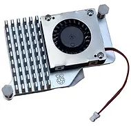
If you use the new Raspberry Pi 5 with the very much recommended $5-or-so Active Cooler, you will find that the mount clips of the Active Cooler make it hard to mount the Pi Cover neatly flush on the back of the Pi.
Fortunately, the solution is simple: drill two holes in the Pi Cover to give those mount point a bit of space. See the picture to the right, click to zoom. It's a simple improvement although the Pi Cover will still fit without the two drilled holes.

Optional Hardware Hacking
It might not be now, but perhaps later. See the 'Hacks' page for improvements and extensions you might want to try on your PiDP-10.
Only one is so nice, that I want to recommend it here. Add one or two standard, 12cm, 5 Volt PC fans to the back panel. You can buy versions that come with a USB connector that goes straight into the Pi. Or, Versions without a USB connector can be wired to connectors on the lamp panel PCB. See the 'hacks page'.
But a 5V, USB powered PC fan is trivial to mount on the back panel and will give you deeply soothing Mainframe Hum & Whirr as a soundscape for the PiDP-10. In fact, the grates behind the fans on the back panel were tweaked to give exactly the right noise (according to a few test people at least).

Recommended: 12cm, 5V standard PC fans. They cost about $8 on places like AliExpress.


