Obsolescence Guaranteed
Recommended: Gigatron
a computer w/o a microprocessor

Connectivity Options & Hacking About
You don't need to read any of this - if all you want is to use your PiDP-10 in the standard way. But because it uses a Raspberry Pi, there is the temptation to configure, customise and hack for extended fun. And if ever you decide to replace the Pi with an FPGA, this becomes even more relevant.
In fact, given the general uselessness of a 45 year old computer, hardware hacking is exactly what could provide motivation to explore its inner guts. So the PiDP-10 circuit board contains:
-
a set of connectors for alternative power options other than the standard Raspberry Pi's own power connector,
-
a set of footprints for RS-232 level converters,
-
an I2C port that can be hooked up to possible extra hardware
(you could add I2C IO chips to provide sensors, hook up more IO, add DA converters to do graphics on oscilloscope displays, etc), -
a connector for a future Maintenance Panel that nobody really needs, but will add to general mainframyness,
- two connectors to optionally hook up home-made spacewar controllers.
This page goes into each of these topics - for those who'd like to tinker!
1. Power Options
You can use the standard USB-C power cable to power the Raspberry Pi directly. The obvious default. I recommend you keep to it.
Alternatively, and this becomes a neccesity if you plug in an FPGA instead of a Pi, you can feed a 5V power supply in to the PiDP itself. Mount a standard USB-C power connector in the provided slot in the back panel, next to it a key switch to turn the machine on. The Pi (or FPGA board) now gets its power through the GPIO connector.
This should give you some flexibility in power options. But it will be especially useful when you decide to replace the Pi with a (planned!) FPGA module!
As per the picture to the right, there are two extra 5V connectors to feed optional 5V fans off. These will work whether you feed power through the Pi's onboard USB power connector or you use this 'alternative' power option.
Shown to the right is the relevant part of both the back panel and the lamp panel PCB with the header footprints you can use on the PCB. The recommended USB-C connector and key switch that fit the mount holes provided in the back panel are shown below, they are easily available.
Modern Pi's draw quite a bit of current. Wire the connectors and switch with a decent gauge.
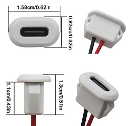
Left: the intended USB-C power connector, a standard type that you can find on places like AliExpress for less than a dollar. Just search for the terms "USB Type C Connector Type-C With card buckle Female 3A High Current Fast Charging Jack Port USB-C Charger Plug Socket"
Right: the intended key switch, about $2 on AliExpress etc. Search for "12mm key switch"
(and do not worry about losing your keys... they are all the same across the whole industry!)


Terminal options:
This gets confusing, because there are multiple options. But there is no such thing as too many options of course.
So, to set the stage:
For a terminal to use your PiDP-10, the logical three choices are either to use the HDMI/USB keyboard connected to your Pi, or use wireless ssh sessions over wifi, or use a classical serial port. This section is about that last option.
There are two types of serial port on the PiDP-10: (1) the built-in serial console of the Pi (its connector is at the top left of the back panel), and (2) you could use up to 4 USB-to-Serial converter cables to get more serial ports. They are less than $2 on places like AliExpress these days.
If you want a serial port, the next choice is whether it will be of the TTL voltage type (the console connector on the back panel is 5V TTL safe), or of the classical RS-232 type (that is, signals of -12 and +12V).
If you prefer RS-232 serial ports, there are yet again two options.
-
The simple one: buy a RS-232-to-USB converter cable. Disadvantage: you have cables dangling out the PiDP-10. Disadvantage 2: not all of these work well with old terminals.
-
The complicated one: use the RS-232 level shifter circuit that the PiDP-10 PCB alread holds. We discuss this below. Advantage: you can use neat DB-9 or DB-25 connectors on the back panel for a more professional look.
First, below the I2C port is a TTL-serial port connector, which can be used with the sort of TTL-serial cables that are popular with Arduinos. It gives access to the Raspberry Pi's built-in serial console. A voltage splitter is onboard the PiDP-10 PCB so you can safely use the more ubiquitous 5V TTL serial cables.
Second, if you want more serial ports (this is a multi-user machine, why limit yourself to only one VT-100 terminal), you can plug the same type of USB-to-TTL-serial cables, but now plugged into the Pi's USB ports. On the TTL end, they can be connected to the RS-232 level shifter circuit described below in the third paragraph.
I will just note that there is a simpler option for getting RS-232: if you use USB-to-RS-232 (not -to-TTL)converter cables, there is no need for any level shifting ciruit. Your vintage terminal can go straight into the Pi then, but you would have a cable dangling out of the PiDP-10, instead of using the neat RS-232 connectors on-board. Also, not all these USB-to-RS-232 converter cables work well with old terminals. It seems to be hit and miss: some of them don't really do proper +12V and -12V signals. Then again, they are about $3 on Aliexpress and the like, so just buy a few different ones.


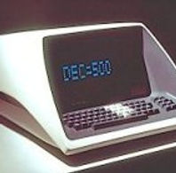
Serial ports & vintage RS-232 terminals
Real serial ports are probably not top of the requirement list for most PiDP-10 users. After all, you can get as many telnet or ssh connections as you want over wifi. But in case you have a real VT-100, VT-220 etc at hand, of course you can connect it to the PiDP-10.
Third: aboard the lamp panel PCB is a circuit for an optional MAX232 level shifter, which converts up to two TTL serial ports to RS-232. The circuit is deliberately left isolated from the rest of the PCB, so you can use it in any way you want. You might want to connect the Pi's internal serial port (from 'first', above), and/or a USB-to-TTL-serial converter cable plugged into the Pi's USB ports. Just wire up the two pin headers shown in the picture below as you want.
And please note: on-board the PiDP-10 lamps panel PCB are two DB-9 connectors. If you like those. But on the back panel of the PiDP-10 there are also two DB-25 connectors, in case you prefer to go the fully period-correct route.
Lastly, why did I not put traces from the MAX232 circuit to the serial connectors? Because in real life, the wiring scheme of serial ports is not always the same. The simple way of letting you run your own wires to the serial connectors mean that you have flexibility.
Here are the schematic and the MAX-232 layout on the PCB. In the middle, you see the headers for two serial ports, the TTL side on top, the RS-232 (which you wire up to the DB-9 or DB-25 connectors) below. The left three pins of each header are for serial port #1, the right-hand pins for serial port #2.
And a warning to close with: the space between PCB and back panel is very tight. It is best to solder the wires in straight to the PCB. Or use an angled pin header.
Option areas on the PCB
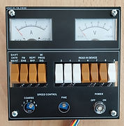
On the lights panel PCB, there is an expansion connector to hook up an optional PDP-10 Maintenance Panel. That panel is not needed to operate the PiDP-10, but it was a special request; I am not alone in my OCD, apparently. At some point I will make a Maintenance Panel for those who are interested (you shouldn't be). Hence the 'MP Connector' at the bottom left of the lamp panel PCB. The current draft MP design is shown to the right for those who care. And again, you shouldn't. It's extra cost and no extra useful functionality ;-)

On the switch panel PCB, there are connectors for two possible spacewar controllers. They would just consist of a few buttons (each needs a diode however) in a box; here they could be connected. If you try, be aware though of the limited clearance above the switch panel PCB in the case! Spacewar controllers would be the first thing to do for those that like to tinker with the PiDP-10... although regular USB controllers/joysticks plugged in to the Pi will do just fine as well. They just won't look authentic. Spacewar controllers are supposed to look home-made, in a wooden box ideally. See the pictures for the ones at the Computer History Museum, although they are for a PDP-1, same idea.
Most important for tinkerers will be the I2C connector (seen from the back, at the top left of the lamp panel PCB). One could add many things, of course, but what comes to mind are the 6 hardware indicator panels mounted atop PDP-10 racks (the picture to the left only shows one) to the simulation, if more Blinkenlights are desired. I would say that makes no sense at all (the PiDP-10 will not suffer intermittent hardware issues), but, nevertheless, if someone decides to make them I'd be eager to get in on the order. If nobody will do it, I might... :-)


