Obsolescence Guaranteed
Recommended: Gigatron
a computer w/o a microprocessor
The PiDP-10: Technical Details
From a hardware perspective, the PiDP is simply a frontpanel for a Raspberry PI. In the hardware section below, the technical details of the front panel are explained. In fact, the front panel can just as easily be driven by any FPGA or microcontroller, it only lights the leds and scans the switch positions.
From a software perspective, the PiDP is just a Raspberry Pi, running Raspbian, which automatically starts up the simh PDP-10 emulator. Driving the front panel means reflecting the state of the PDP-10 CPU through the leds, and responding to the switch settings.
1. Hardware
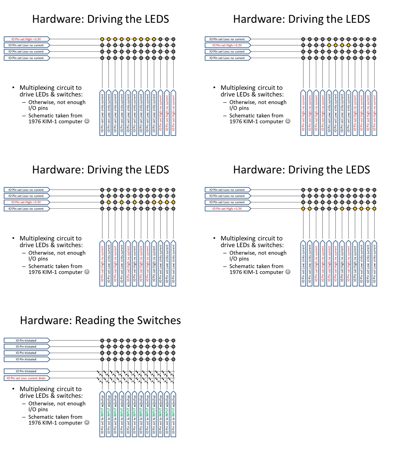
The Raspberry Pi has a 40-pin GPIO connector which drives the front panel. The schematic is actually taken from the venerable KIM-1 single board computer, and I used it for my earlier PiDP-8 and PiDP-11 replicas too. A multiplexing scheme is used to quickly light up alternating rows of leds in sequence. Doing so approximately 60 times per second, with the switch positions scanned in-between, the human eye sees the whole front panel light up.
The figure below gives the basic idea. Three groups of GPIO pins are used:
-
7 'ledRow' pins, each of which provides a collective power line ('+') to a row of 18 LEDs.
-
18 'column' pins, which are connected to the cathodes ('-') of the individual 18 LEDs across all ledRows. So a row of LEDs is powered up when a ledRow pin is set to Output High. Which of the 18 LEDs actually lights up depends on whether its column pin is set to Output High (LED off) or Output Low (current flows, so LED lights up).
-
5 'switchrow' pins each provide a power sink (0V) to a row of 18 switches. The column pins above, when flipped to Input mode with pullup resistors, can then sense which of the switches is 'on' (because that causes a short from row to its column pin overriding its weak pullup resistor).

The software quickly cycles through the 7 ledRows, setting each them High in sequence. Do it fast enough and the human eye sees all rows light up consistently without flickering. Then, the 18 column pins are quickly flipped over to being input pins to sense their attached switches, and the cycle starts afresh.
The simplified animation below pretty much illustrates the principle. Click to zoom:

Download the high-res PDF schematics from the PDF viewer above.
Adding I/O pins to drive the front panel
The Pi has a decent amount of IO pins, but alas, the PDP-10 front panel needs more to drive its 124 LEDs and 74 switches.
A 74HC138 decoder/multiplexer IC was used to drive the 5 switchrows (its output low to the activated switchrow is what is needed, as the switchrows, when enabled, need to sink current from actuated switches).
For the LED's ledrows, a 74HC238 is used, as they need to provide +5V when selected. The wiring is such, that it is impossible to enable both a ledrow and a switchrow.
Note that the Pi's 3.3v ledrow signal is routed to what could be called a buffer IC (a 2981 Darlington array) to provide both 5V and sufficient mA's to drive a row of 18 LEDs at the same time.

Replicating the PDP-10 front panel case
The whole story is in one of my blog posts (link), but this is what made the PiDP-10 such a big project. Originally, it was planned to live in a wooden case - but that really did not give the right 'experience'. After my PiDP-11 I promised myself not to do injection molding again, but here is the PiDP-10 injection mold nevertheless:

An injection mold of this size (the picture shows one half of one of the two molds only) is a nightmare for hobbyists.
Not only does it cost a fortune (that's the reason the PiDP-10 costs $370), making an injection mold is also a high-risk undertaking. If your 3D CAD model is somehow wrong - the plastic does not flow well enough, the plastic parts do not separate easily from the mold - you've just bought yourself a very expensive boat anchor... And then, there is the risk of thermal deformation. A part this size, coming out of the mold too quickly, shrinks and warps. So special precautions had to be taken. It scared the daylights out of me.
With the PiDP-11 I did the mold design mostly myself. This time, given the size and complexity of two molds (bottom and top), both more than half a meter wide, I got a specialist company involved.
We went through endless iterations, but after 18 months it was done. Shown below are some of the early designs we went through. It is not the final case, you will see imperfections and changes from the final mold - that is why it took 18 months in the end. I guess this is more a postcard to myself than anything of interest to others, but never mind!
Circuit board layout
The PCB is made in Kicad (what would we do without Kicad!), and using freerouter. It is a very simple affair, as it's all simple point-to-point wiring from the Pi's GPIO pins, through the 3 ICs, to the LEDs and switches.
There are two 'complications': first, the LEDrow pins demand more mA than the Pi can provide. Therefore, a UDN2981 (or modern equivalent) chip acts to buffer these lines and provide more current to the LEDs. Secondly, all the GPIO pins are protected by resistors to limit the load on the GPIO pins. 220 (or 270) ohm resistors limit the current to the LEDs; 520 ohm resistors limit the current sunk during the switch sensing.
As the Raspberry 5 came out when I was designing the PCB, I decided to add in some heat vents right above the Pi 5's little fan and its heatsink. Alternatively, when you add the big 12cm PC fans on the back panel, the little fan can be left out (personal issue, I hate the noise of tiny fans). In which case, the vents add airflow where it is most needed.
Click on the front and back pictures below for high-res images.


Option areas on the PCB
On the lights panel PCB, there is an expansion connector to hook up an optional PDP-10 Maintenance Panel. That panel is not needed to operate the PiDP-10, but it was a special request; I am not alone in my OCD... At some point I will make one for those who are interested (you shouldn't be). Hence the 'MP Connector' at the bottom left. The current MP design is shown to the right for those who care.
On the switch panel PCB, there are connectors for two possible spacewar controllers. They would just consist of a few buttons (each needs a diode however) in a box; here they could be connected. If you try, be aware though of the limited clearance above the switch panel PCB in the case! Those would be the first thing to do for those that like to tinker with the PiDP-10... although USB controllers plugged in to the Pi will do just fine as well.


Most important for tinkerers will be the I2C connector (seen from the back, at the top left).
One could add many things, of course, but what comes to mind are the 6 hardware indicators mounted atop the PDP-10 racks to the simulation, if more Blinkenlights are desired. I would say that makes no sense at all (the PiDP-10 will not suffer intermittent hardware issues), but then, nevertheless, if someone decides to make them I'd be eager to get in on the order :-)
2. Software Concept
The PiDP-10 is intended to feel like a machine with two cores.
There is the Raspberry Pi/Linux 'core', which remains fully usable, and at the same time, there is the PDP-10 core running in parallel. Admittedly, the PDP-10 is only a 'soft CPU', but the idea remains the same.
The Pi starts up the PDP-10 simulation when it is powered on, but the PDP-10 'core' just runs a tiny 'running lights' program, idling away, until the user triggers the boot process of the PDP-10.
Like on the real machine, the boot process starts with the user pressing the READ IN switch. That switch clears the CPU and I/O devices, then starts reading data in from a specific I/O device to boot up. On the real machine, the I/O device to boot from is set through dedicated device select switches on the Maintenance Panel. The PiDP-10 reads the rightmost 7 data switches on the front panel at the moment it powers up, and stores the settings in a virtual Maintenance Panel. After that, those 7 data switches are freed up for normal use as the user sees fit.
During the boot process, the PDP-10 will probably need some operator commands on the console port. On the real machine, a Teletype 33 would normally be attached to the console port. On the PiDP-10, the user must start a telnet connection to the PDP-10 console port instead.
When the boot process has completed, a normal PDP-10 user would rather not do his work from the Teletype console, but from a much more comfortable serial terminal. So it is for the PiDP-10. Included are many terminal types to choose from, just as the AI Lab contained all sorts of terminals.
But on the PiDP-10, of course, although hook up a real serial terminal over the serial ports of the machine, most likely you will be using a simulated terminal. Virtual VT-52, VT-05, Datapoint 3300, Imlac and more are available. These simulated terminals obviously do not connect over an actual serial port, but over a telnet connection. That also means that the simulated terminal does not have to run on the Pi. It might just run on a laptop and connect through Wifi. For the PDP-10 'core', that is all invisible. It just sees serial ports.
The actual software (more important than the 'concept')
The PDP-10 KA10 simulator was written by Rich Cornwell, within the simh group. Rich will build support for the PiDP-10 into his simulator, and the PiDP-10 github will thus mirror his official version. Rich's github is at https://github.com/rcornwell/sims.
Around that simulator are a lot of others quietly doing their work. Each of the terminal types is a standalone simulator, of course, but there are separate PDP-11 simulators running to support both the Knight TV terminals and the GT-40. The Imlac is another separate simulation; as is the PDP-6 that is connected to the PDP-10 through shared memory. The PDP-6 simulator was written by Angelo Papenhoff, as are many of the other AI Lab components, in cooperation with Lars Brinkhoff.
<much more needs to be written here, forthcoming>
3. FPGA Version
As of February 2024, there are people working on an FPGA module that can be plugged in, instead of the Raspberry Pi. More details will follow.
Source code/downloads
Note that you can run the PiDP-10 software on any Raspberry Pi without the actual PiDP-10 hardware. Although you'd be blinkenless, the software runs fine.
<more info to come>
The PiDP-10 sofware can be installed on a regular 64-bit Raspberry Pi OS. It is compatible with the Pi 5.
Installation steps:
<cd ~>
<git clone URL>
<~/install/install.sh>
<more info to come>
The PiDP-10 schematics can be downloaded from further up on this page.
A user manual is forthcoming (April 2024) after the first betatester's feedback.


